Installation GuidesUpdated 3 months ago
View and download installation guide for whole home / business water treatment systems Download Here
Set up
Before you begin, be prepared, read all instructions and you’ll need to make sure you have all of the plumbing valves for bypass, pipes, 1” male NPT fittings for system connections, 3/4” ID vinyl drain tubing and tools that are required. Also, we recommend you have diluted bleach-water for disinfection. (Dilute household bleach ¼ cup to a gallon of water. Note: it is critical to read and follow safety instructions with any product you use.)
Also, for Systems with a sediment and/or carbon filter (noted by having an S or T in the System part number), two 0-100 psi pressure gauges (1/8” NPT) are optional.
To hang your ICS System, find a wall near your main supply line. Be certain the wall will support the System’s weight -- do not hang directly on drywall. If necessary, use a board, strut or similar to span 2 wall studs. Then anchor the board to wall studs and hang the System on the board. The System itself might weigh more than 50 lbs, so make sure the wall or board you mount to can hold at least 100 lbs. Also, be sure to leave a minimum 6” clearance below the System to allow for filter changes.
If an inside location is not ideal, you can install the System outside. But keep it out of direct sun and in a place that will not freeze or exceed 113 degrees Fahrenheit. And when it comes to where in your piping to install, you’ll typically want to put it after irrigation and before anything else. If installing on a well water system, be sure to install it after the pressure tank.
As you prepare to install the System, make sure you can protect the wall and floor around it from any water spillage (which can happen during installation).
Before installation, be sure to flush the hot water heater. This will remove as much minerals as possible from the tank, reducing the time until the treated water is at its best.
Mounting
First, remove the filter(s). If the System has more than one filter, make a note of which housing filters come from, filters must be re-installed in the same order.
Mark the housing with the installation date. This will be a helpful reminder in the future.
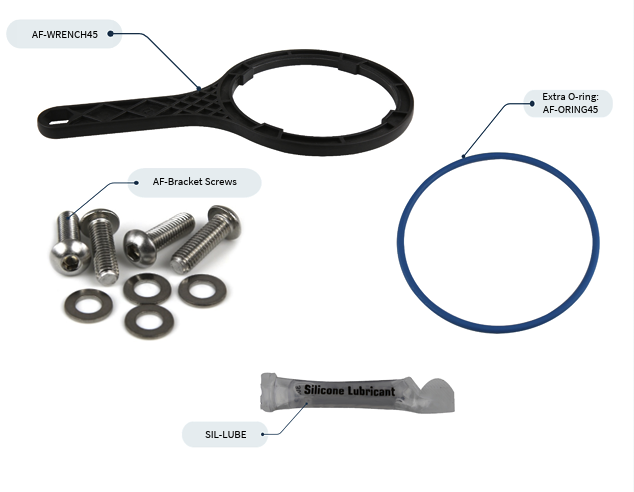
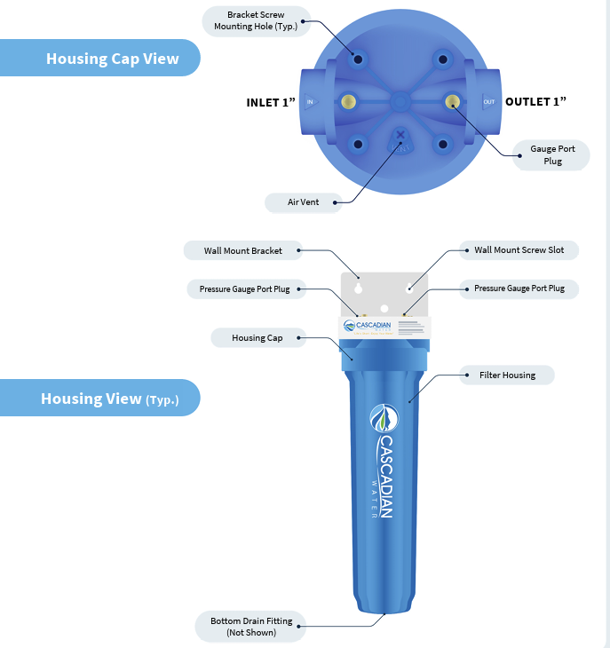
The inlet and outlet are marked on housing cap. Housing cap may be rotated so the inlet is on the left or right to suit your requirements. Connect the Wall Mount Bracket to the Housing Cap with provided stainless steel screws and washers. It is a good idea to mark the inlet and outlet so it’s easy to see.
Next, mount the Bracket with Cap on a solid, flat, and vertical surface or board spanning wall studs making sure Bracket and Cap are level. See “Set up” above for more details.
Plumbing the ICS System
To control the flow of water during installation and maintenance, begin by installing valves on the inlet and outlet. Caution: Use only Teflon® tape to seal threads -- do not use thread sealant or sealing compound.
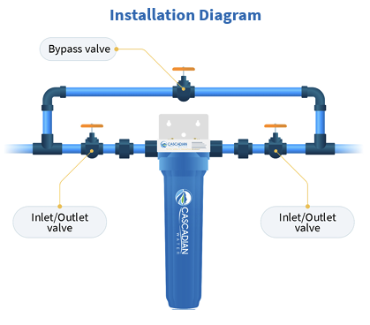
For ease of future maintenance install a bypass assembly around the ICS System (see Installation Diagram below). A bypass allows for water downstream during filter changes or if a leak develops in the System and is required by plumbing codes.
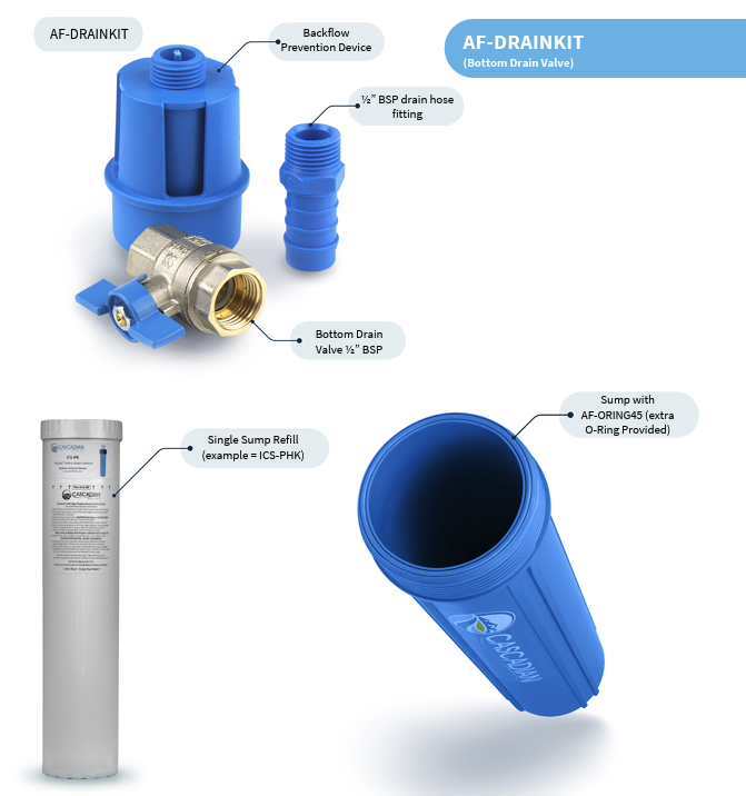
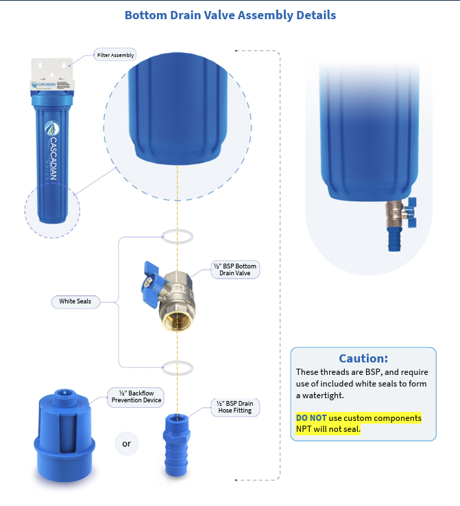
Install the included Bottom Drain Valve (BDV) on Filter Housing nipple. Remove the black shipping cap from the Housing nipple and discard. Only use parts that come with the System and not custom fittings. See diagram – Bottom Drain Valve Assembly Details. BDV components and Housing nipple are all European thread, and they will leak if used with standard NPT pipe thread.
Connect the BDV to drain: you’ll have two different options. The first option, the larger fitting, is the backflow prevention device. The second option, the smaller barbed fitting, is for routing ½” tubing (not supplied) to drain or a clean bucket to collect water during filter changes.
Connect the Filter Housing to the Housing Cap. DO NOT use the filter wrench to tighten the housings to the cap. This will cause it to be too tight. After insuring there is an O-Ring in the groove simply tighten the housings by hand, allowing the lubricated O-ring to make the seal. Note: we do supply an extra O-ring with you system.
DO NOT use petroleum-based products to lubricate the O-ring. Use only silicon lubricant (Cascadian product number: SIL-LUBE) which is included with your ICS System.
DO NOT use any type of thread sealant or tape on the housing to cap threads. If a leak develops, replace the O-ring lubricated with Cascadian SIL-LUBE.
Once the above has been completed, connect the plumbing to the ICS System.
Checking for leaks
Close all valves. Then loosen the air vent on the top of each filter housing (see diagram - Housing Cap View) and slowly turn on the water inlet valve, allowing the air to escape. Close the air vent when all of the air is out. Check for leaks.
Repairing Leaks
If there is a leak where the Filter Housing meets the Housing Cap, turn off the water valves and use the vent to relieve pressure. Then drain the System by opening the BDV. You may need a wrench to loosen the leaking housing. Once loosened, check the O-ring for damage (replace if needed); check the O-ring groove for debris; reinstall clean lubricated O-ring and hand tighten housing to cap. Once complete, close the vent and BDV. Then check again for leaks.
If there is a leak where plumbing connects to the inlet or outlet Do Not Overtighten. Damage caused by overtightening is NOT covered by warranty. Repair by removing the fitting from Housing Cap, carefully clean threads of existing Teflon® tape and reapply new Teflon® tape using slightly more tape than the first time. Then reassemble then check for leaks again.
Install Filter(s)
To install the filters, first drain the housing(s). Start by turning off the water Inlet and Outlet valves and open the Bypass valve (if present) and use the Air Vent valve to relieve pressure. Then, empty the housing by opening the BDV. Once empty, use a wrench (if needed) to remove the housing(s). Caution: the housings will be heavy, so take precautions do not drop and damage Housing or BDV.
If used filters are present remove and dispose of them. At this point, it’s important to stop and disinfect the housing(s) prior to installing the cartridges. That includes washing your hands, but also wiping the inside with a clean cloth and diluted bleach. After complete, close the BDV.
Important Notes
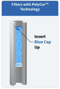
If you’re using a PolyCor filter System, then make sure to insert the Blue Cap up in the housing.
If you’re using an ICS-P, ICS-PH or ICS-H, then install the gasketed end up.
Any other filters can go either way.
Remove the protective wrap on the filter. If installing more than one System or a two-filter System remove protective wrap one at a time taking note as to which filter goes into which housing.
For proper operation be sure to install the filter(s) in their specified order.
From here, once complete, hand-tighten (DO NOT use the Housing Wrench) to re-install the Filter Housing to Filter Cap.
At this point, you’re ready to check for leaks again following the same process outlined above.
 Prepare for Use
Final steps to finish installation.
Start by closing all valves: Inlet, Outlet, Bottom Drain, Bypass Valve and the Air Vent.
Open Air Vent approximately 1 complete turn.
Open inlet valve just enough to let water flow slowly. This will fill the Housing and force air out the Air Vent. When air has escaped water begins to flow out the Air Vent close the Air Vent.
Clear any air and filter fines.
Fully open a treated water tap downstream.
Let the water run, usually around five minutes, or until it runs clear. Once the water is clear, all filter fines and air bubbles will be out of the treatment system and plumbing.